Android utility
Turn it on
First, connect the device to a network adapter via USB. The frond-side LED will glow continuously, then double LED-blinking will inform you about Bluetooth channel selection.
Connecting to the BlueDSO device
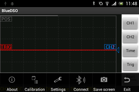
Start the BlueDSO software, select the “Connect” icon from the main menu and select the BlueDSO device to connect to.
On the status bar, the “Connected” state appears when you’ve successfully connected.
Buttons:
On the right-hand side of the BlueDSO for Android software there are four on-screen buttons for setting preferences and a fifth “Start” button for starting the measurment. These buttons allows you to change measuring range and set trigger conditions.
Input voltage dividers
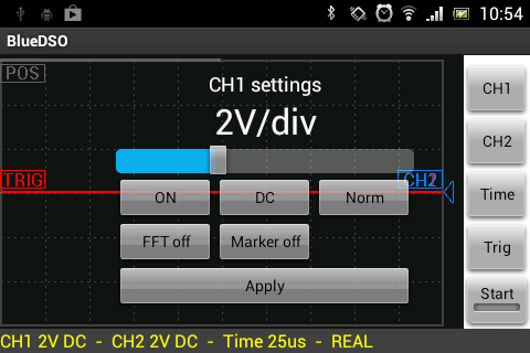
When either CH1 or CH2 is selected, you can set the range of the selected channel with horizontal skip bar.
you can set the selected channel’s vertical position with (vertical) touch gestures.
Pressing the “Range” button makes the status bar red. Then, you can set the range of the selected channel.
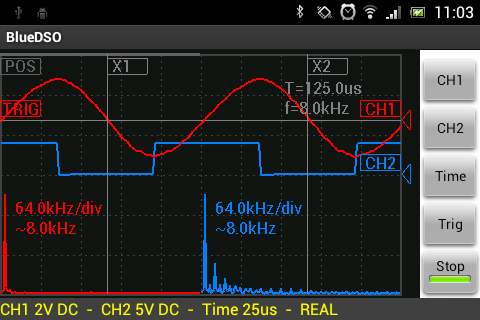
The ON-OFF button is used for turning the selected channel on/off, the DC-AC button is for enabling/disabling the galvanic isolation, which is inactive, when DC is selected, active it AC is selected. The Norm-Inv button is used for inverting the signal of the selected channel. The FFT button is used for turning on the Fast Fourier analisis, the Marker button is turning the vertical markers on/off.
The vertical position of the channels’ signals can be moved with the CH1/CH2 draggable element.
Time base
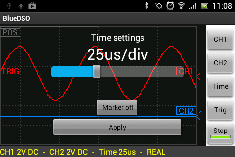
When “Time” is selected you can set the time base used by the BlueDSO device in the range of 250ns/div – 250 ms/div. The time base used by the BlueDSO device can be set within the range of 250ns/div – 250 ms/div.
In 5us/div – 250ms/div range the device samples both channels’ signal real-time, so any kind of periodic or transient signal can be observed with the device.
In the 250ns/div – 2,5us/div range the sampling is not real-time, the device does the so-called “Equivalent Time” sampling, therefore in this range only periodic signals’ observation would result in useful information.
The Marker button is turning the horizontal markers on/off.
The horizontal position of the channels’ signals can be moved with the POS draggable element, so transient signals can be observed beyond the display matices’ limitations.
Trigger
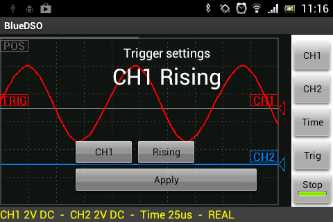
When “Trig” is selected, the trigger source (CH1 – CH2 – Line) and mode (Rising–Falling) can be set. Selecting CH1 or CH2 makes the trigger sensitive for that channel. If the source is set to “Line”, the signal processing takes place without triggering. The “Falling” and “Rising” options make the trigger sensitive to the edge selected.
Trigger level can be set with the TRIG draggable element.
Calibration
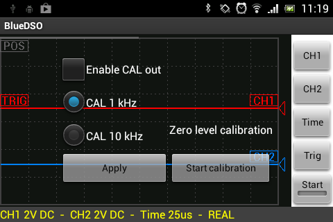
Either a 1kHz or a 10kHz square wave can be connected to the device’s front-side “CAL” output by selecting the “Calibration” icon from the system menu. The amplitude of the square wave is approx. 3.3V.
Settings
Settings can be found in the system menu.
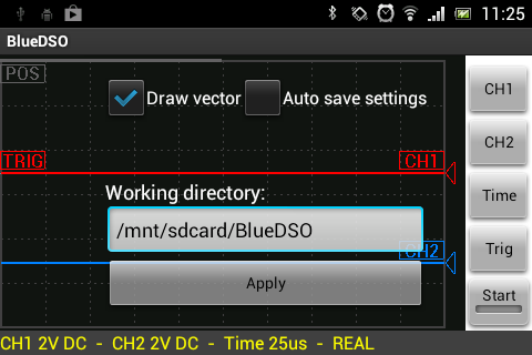
Auto save settings: with this option enabled, ranges and all other settings are saved automatically and restored on relaunch.
Draw vector: this option toggles visualisation to show the result either as a continuous line (checked) or a set of dots (not checked).



 Visit Today : 36
 Who's Online : 1